ATLAS/Engineering

Engineering.

Every site gets its own design and its own calculations. Below, one table goes together part by part.

Assembly, in order
01/ 06

Foundation

It starts below the ground line. The foundation type comes from the site's soil data, then it is driven or set to depth.

Post

The post carries everything above it down to the foundation. Its length follows the grade, so the table stays true.

Clamp

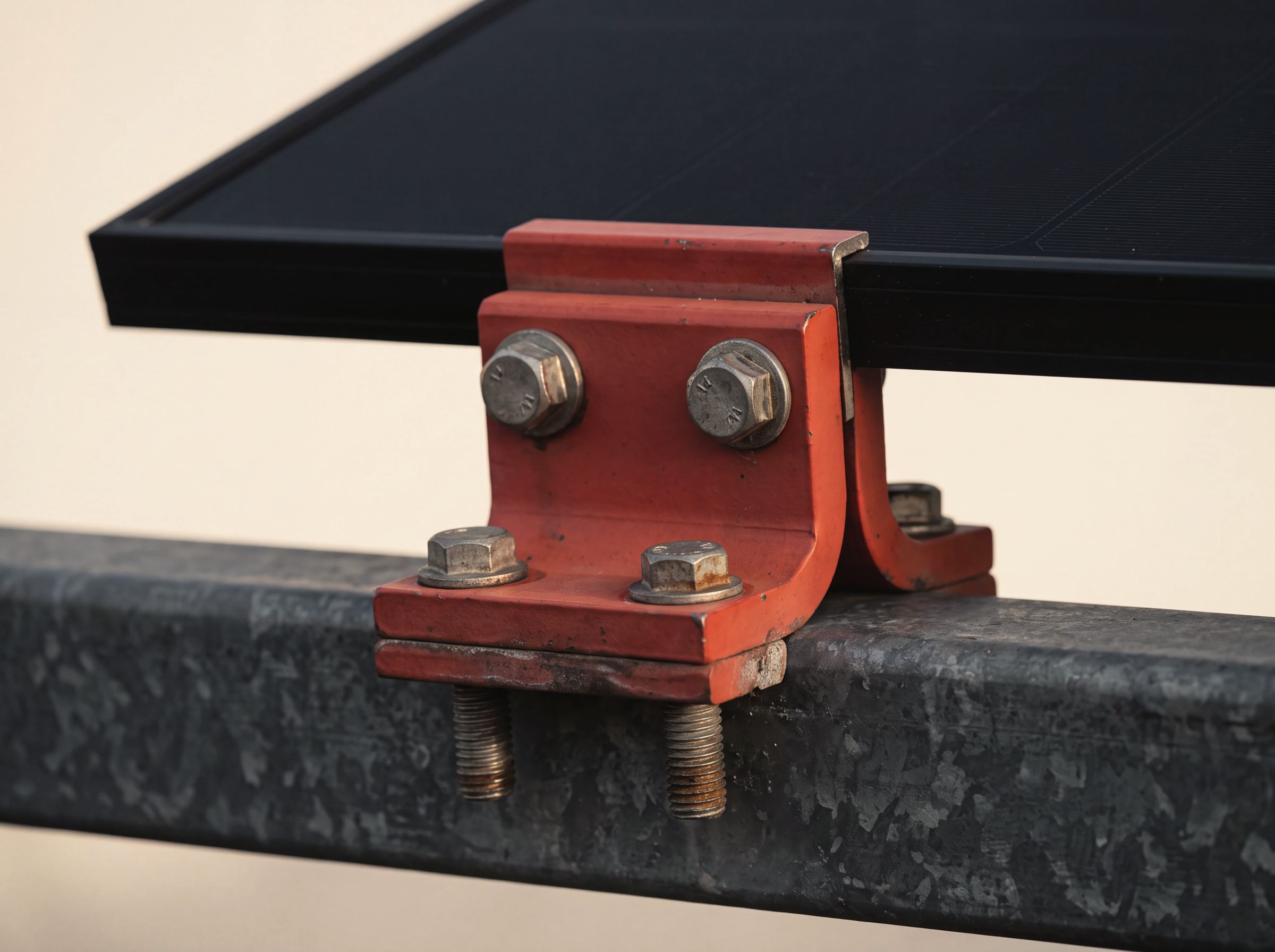
The clamp joins post to rail. It is where load changes direction, so it is sized for the worst case it will see.

Rail

The rail spans the table and sets the tilt. One profile across the whole table keeps the kit short.

Panel

The panel goes on last, and takes the weather first: wind lifts it, snow sits on it.

The load path

Now follow it back down: panel to rail, rail to clamp, clamp to post, post to ground. Every A is a load path.
GROUND LINE0102030405
What we design for

The conditions on site.

Every project is designed to the codes and standards that govern its location.

Wind

Uplift and pressure

Calculated for the site's exposure and the array's height and tilt.

Snow

Weight and drift

Including drifting against parapets and rooftop equipment.

Seismic

Ground movement

Where the location calls for it.

Corrosion

Finish and material

Chosen for the site's environment and its design life.

A vermilion clamp bracket bolted to a railClamp detail
The design package

What your team receives.

  • Layout drawings for the array or building
  • Structural calculations for the site
  • Attachment and foundation details
  • Bill of materials, kitted to the layout
  • Install guide in build order

Put an engineer on it early.

The cheapest time to get a structure right is before anything is ordered.